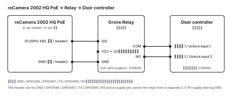
- Identify the header pins (vendor wiki): GND, GPIO488, GPIO487, TX, GPIO490, RX. The three IO ports are D1 = GPIO490, CLK = GPIO487, SMD = GPIO488; this solution uses D1.
- The header has no supply pin, so the relay's VCC comes from elsewhere - see "Powering the relay" below. A GPIO drives 3.3 V logic levels while the Grove Relay draws 100 mA, so the GPIO carries SIG only. This route needs no XIAO.
- The levels are undocumented. Measure GPIO490's high level with a multimeter before connecting the relay.
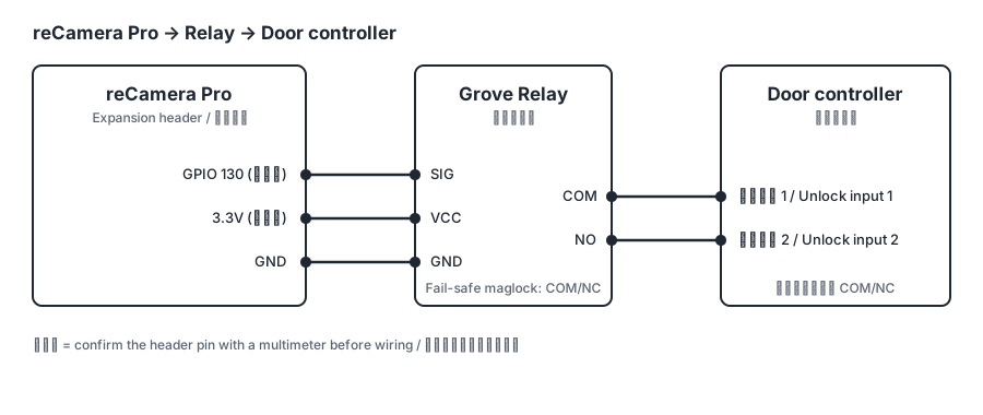
- Connect three wires, leaving the relay's NC wire unconnected: header GPIO490 → relay SIG, 5 V → VCC, header GND → GND (the supply's ground lands here too).
- Test with an LED first. Put an LED with a series resistor between GPIO490 and GND, deploy, and check that it lights once for the configured pulse width. Then swap in the relay.
- Confirm one click per pulse. If the relay does not click, go back to step 3 and re-check the level.
- Connect the door controller. Relay COM and NO go to its unlock input; neither terminal carries any voltage of ours. A lock that opens on power loss needs a normally-closed contact, which the Grove Relay does not have — use the Grove SPDT Relay 30A (SKU 103020012) and wire COM and NC.
- In the form, fill Device ID and Actuator ID. Face Library URL, Match Threshold and the signing key are carried over from Step 1; change the URL only if the camera reaches the server at a different address. Then deploy.
Powering the relay. Either works:
External 5 V - a 5 V USB charger, or the door side's existing 12 V stepped down to 5 V, with its ground tied to the header GND. Nothing on the board is touched.
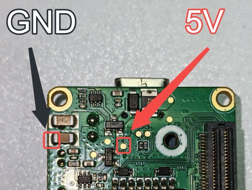
Soldered to the board - the B3 PoE baseboard (v1.2) has 5 V and GND pads, marked in the photo below; solder two wires there. PoE power is limited (2 A fuse on the board, 1.2 A nominal on the main rail) and the relay's 100 mA fits in that headroom. Confirm both pads with a multimeter before soldering.